Parallel Port Pic Programmer for ICSP
My faithful programmer bit the dust, so I needed a
programmer to work with my WIN98 system. I do not have USB on this
machine, so the simplest way to go was to build what was needed. This
is the result of that very specific need. I do not need to program
anything that is not in the 16F family and all my projects are designed
to use ICSP. I had all the parts on hand, left over from a "No Parts
Pic Programmer" from many years ago.
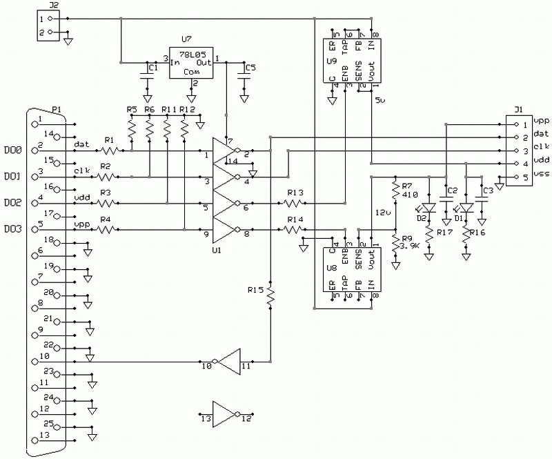
R7 is made up of two 820 ohm resistors in parallel. I did not find any 410 ohm standard parts.
The 16F family are specified for Vpp of 10 to 13.6 volts so no exotic voltages are required to power this.
I am using the program from Oshonsoft.com, which is really cool. It allows inverting the lines. Handy if you don't know anything about the port.
The program is here (this an executable, so right click and "save as")
The program (maybe all programs) does not recognize whether or not there is anything connected to the parallel port. It will not verify the chip if there are some issues. The problem I seemed to encounter, that was baffling, is using the wrong PIC source code. The programmer tries to determine what PIC it is programming, and if the code does not match the PIC selected, it acts as if there is no connection to the PIC. It does not tell you that it is wrong, but does not seem to do anything. Just the same as having nothing connected !! If you can't seem to program the chip, check that the screen entry is correct for the chip you want to program.
I added sinks on D0 - D3 so the outputs at J1 are pulled low if there is no parallel port connection. R1 - R4 provide current limiting to protect the PC port in case something goes nuts. D1 and D2 discharge the caps (C1 and C2), and also function as indicators that something is happening.

The shematic file is here
and the board file is here
The software for the schematic and board is here ExpressPCB
print out the BOM from the schematic for the parts list.
R7 is made up of two 820 ohm resistors in parallel. I did not find any 410 ohm standard parts.
The 16F family are specified for Vpp of 10 to 13.6 volts so no exotic voltages are required to power this.
I am using the program from Oshonsoft.com, which is really cool. It allows inverting the lines. Handy if you don't know anything about the port.
The program is here (this an executable, so right click and "save as")
The program (maybe all programs) does not recognize whether or not there is anything connected to the parallel port. It will not verify the chip if there are some issues. The problem I seemed to encounter, that was baffling, is using the wrong PIC source code. The programmer tries to determine what PIC it is programming, and if the code does not match the PIC selected, it acts as if there is no connection to the PIC. It does not tell you that it is wrong, but does not seem to do anything. Just the same as having nothing connected !! If you can't seem to program the chip, check that the screen entry is correct for the chip you want to program.
I added sinks on D0 - D3 so the outputs at J1 are pulled low if there is no parallel port connection. R1 - R4 provide current limiting to protect the PC port in case something goes nuts. D1 and D2 discharge the caps (C1 and C2), and also function as indicators that something is happening.

The shematic file is here
and the board file is here
The software for the schematic and board is here ExpressPCB
print out the BOM from the schematic for the parts list.