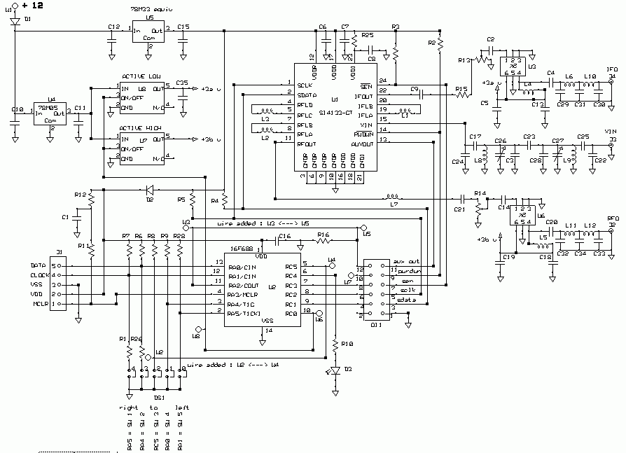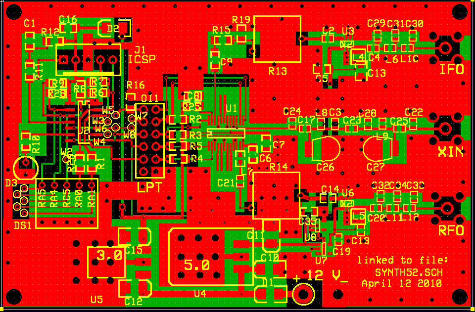
The SI4133 is the full blown dual conversion synthesizer.
I find this most useful as a marker frequency generator, capable of
providing markers ( not weak) on all amateur bands from 144 MHz through
24 GHz.
This may not be as useful as locking all your transverters to a 10
M reference, but only one marker unit is required.
It is also useful as a beacon generator using the PA regulator as the keying, and controlled by the PIC. Beacon
The synthesizer is programmed from a PIC when power is applied, or it may be reprogrammed to a different frequency by using a 5 position DIP switch to select from 32 possible frequencies and the MCLR reset. It can be a neat lab tool since it will interface with the parallel port of a PC and frequencies can be anything you want. (within its capabilities.)
ordering boards from ExpressPCB
Features:
Serial programmable synthesizer with loop filter, VCO and programmable
dividers on the chip
In circuit serial programming
Can be controlled with the Silicon Labs software, under windows GUI, via the paralell port of a PC.
Switch selectable frequencies from the onboard PIC from any of the three synthesizers.
PIC enters sleep mode after programming the synthesizer. Awake from sleep on lock error signal.
Awake from sleep via pushbutton for new freq entry
Switches can be panel mounted (useful if used as a marker in box)
External 10 MHz reference input ( 2- 50 MHz)
Tunable 10 MHz reference bandpass filter
Adjustable output level up to +12 dbm or so.
output low pass filter on both outputs.
Source Code (this has the marker frequencies, 144.2, 222.1, 432.1, 903.1, 1296.1 and 1152 and a few others)
More source code and HEX files
Data Sheet for SI4133 synthesizer (a PDF file) pins are a little different between the SI4112 and SI4133. Make sure which column you are working in as they are in the same table.


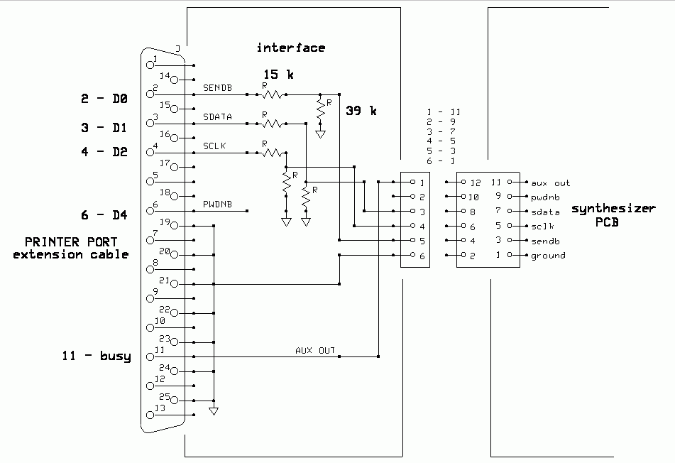
Used with the Silicon Labs software, the interface above allows easy control of the project from the paralell port. (Printer Port)
OI1 is the outboard interface connector, a simple DIP connector with .1" spacing. Normal operation with the onboard PIC has 2 position shunts shorting across adjacent pins. To use the LPT interface the shunts are removed and a single row connector from the interface is connected to the odd numbered row.
When U7 and U8 are used as shown, the PIC is still controlling the power to the amplifiers, U3 and U6. This means that if you are testing with the windows programmer, there needs to be an entry programmed in the PIC and selected by the dip switch to enable the appropriate amplifier.
The voltage divider network was chosen to match the LPT level to the synthesizer. I measured the voltage from the LPT port before settling on these values. I do not have 5 volts from the LPT port, it was considerably less.