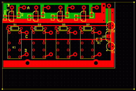
Not a really great picture, but if you are familiar with ExpressPCB, this is laid out as a mini board order. This would not be too difficult to scratch out with a Dremel tool, by hand, and use leaded components. This is the same as the schematic on the first page, but repeated three more times. R1 provides current limiting for all modules. The operation is +5 from the control unit goes to A, Q1 conducts pulling B near ground, starting the sequencer. The sequencer sends a ground back to C when it gets to event 3 grounding the relay coil. When the contacts of K1 close, the +5 from the 78L05 is sent to the TX line going to the 1296 band module.
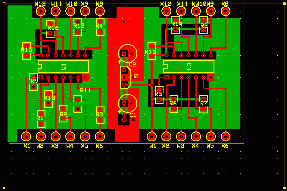
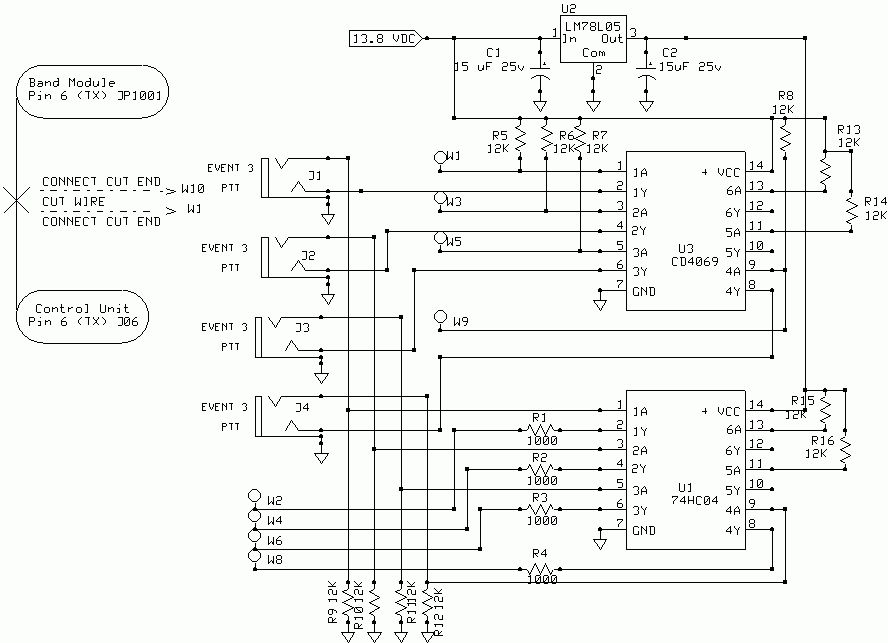
I tried using a 7404, and 74HC04 hex inverter, but the sequencer thinks +5 is the same as ground, so it won't work directly. It seemed like a neat idea, but the various logic levels take some adapting, then it's just getting way to complex. Another idea was to use one 74HC04 and one CD4069. Run the 74HC04 on 5 volts and the CD4069 on 12 volts. The sequencer would be happy with that, and you also have enough sections to do all 4 bands.. Again it's getting really complex. It would look something like the board below.


If anyone is interested in doing boards, I'm good for
one !! I don't plan to order any myself. If you do something with this,
don't forget to add mounting holes. Also if anyone wants copies of the
Express PC files, just ask. kd7ts at comcast.net or kd7ts at aceweb.com.
previous page
previous page