UPDATED: March 9 2009 FT-736R sequencer
The inspiration for this came from interfacing a Yaesu FT736R with a 1296 amplifier from W6PQL.
There is a potential problem if the amplifiers 28 volt supply is not on. To avoid this purchased the "all purpose amplifier controller" with the amplifier and incorporated all the features provided in the universal amplifier controller board. This will probably work with the 4 event sequencer as well, but I did not have one to experiment with, so can only report results with the all purpose amplifier controller board and the 2 X 286 amplifier.
What makes this possible is an easy modification to the 736. This applies only to one "band module", in my case, 1296. The module keying is done by one wire, called TX on the schematic. This wire is routed from the control unit to the 1296 module and runs over the wall behind the front panel. The voltage used to key the module is +5 volts in transmit, and 0 volts in receive. The band module control circuit acts as a current sink, so while the module is keyed, the voltage measured on this wire is about one junction above ground. (.7 volts) We need to use this +5 to send a ground to the sequencer to initiate the transition from receive to transmit. .7 volts is not enough to keep the sequencer keyed, so the TX from the control unit is dedicated to keying the sequencer and the 5 volts to key the band module is from a different source, but still dependent on the sequencer. Due to the way the sequencer works, we need to do logic inversion twice. The transistor does it once to drive the sequencer, and the relay does it once to apply 5 volts to the band module.
While I was doing this I removed the 1296 module and turned the level down to 10 watts. It was putting out more than 16 watts prior to this. The covers do not need to be removed from the module to do this. Yaesu engineers thoughtfully provided access to the level and ALC pots through the cover. The module does need to be removed to access the bottom cover.
Some discussion of the 736 control is in order to see how this works. All of the the functions that initiate transmit are common to the PTT buss and are read by the microprocessor without distinction. This includes MOX, VOX, PTT and some tone ID functions. Band modules are put into transmit according to what band is selected, and almost instantly, but only the selected band. The accessory keying jack labeled "standby" is only a few electrons behind the PTT, and not useful to prevent hot switching.
Why this works is the 736 band module cannot transmit until the sequencer enables the band module TX line. When PTT is enabled TX for the selected band goes high and is converted to a low by the NPN transistor. This is sent out to the sequencer mounted in the PA and the sequence is initiated. Fans run, antenna relay switches, bias is applied to the PA and a ground is sent back to a relay I added in the TX line in the 736, to send the 5 volts to the band module, and transmit is enabled for the band module. Since this is a sequencer, going back to receive is the reverse order. This is not dependent on mode, so it works with SSB, CW, FM, VOX, MOX or anything that transmits.
I considered using the PTT to initiate the sequencer, but since it is common to all functions, the 1296 sequencer would be keyed even if 432 or some other band is selected. If I had more accessories then they would all key from the PTT at the same time. Further, if you key from the PTT, it is already too late to start the T/R sequence because the 736 makes power in just microseconds. I needed something on the order of 10s of milliseconds. It took some tracing and testing to see how this works, but it is actually quite simple. Using the TX line on each individual module allows having separate amps or preamps that are sequenced, per band, individually, and TX initiates within a few microseconds of PTT. The advantage is that I never generate power until the sequencer allows it. The down side is that a separate relay, transistor and jack are required on each band, as well as an external sequencer for each band. The parts are small and 4 bands worth of switching could fit on one single sided board.

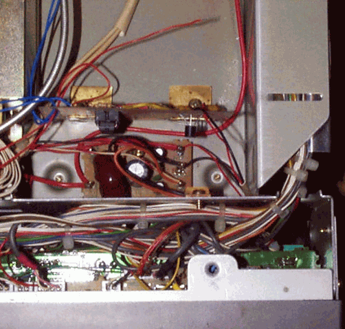
I mounted the transistor and 5 volt regulator and relay on the screws that hold the 115 VAC switching supply. This is visible above as the brass squares above the board. +12 and ground are handy on the regulator board about one inch away. I used an 1/8th inch stereo jack to get the keying in and out. There is a small area between the end of the heatsink and the side where the stereo jack can be mounted. It is useful to temporarily move the power supply to allow access to the inside of the back.

Peek inside between the supply and the side and you can identify the area where the jack can be mounted. There is very little room, so be sure the jack will fit when the supply is in position. I do not use the internal supply, so I removed it, and have plenty of room . There is also the possibility of mounting a bracket to the back to hold a jack to the outside. It's pretty easy to get a couple of wires through the back. I'm sure someone will come up with a creative method.
There are likely other methods that would serve to protect the preamp from the transmit power, but this is what I came up with. It works very well. The 5 volts was included with the thought I would install the preamp inside the 736, and this would also be the 5 volts for the preamp. As it turns out, I included a 5 volt regulator in the preamp case.
I am using the same 28 volts that supplies the amplifier, to power the sequencer and relays. This is an important point. If the sequencer and relays have separate supplies, then you are back to square one, and this will not protect from lapses in testing and operating.

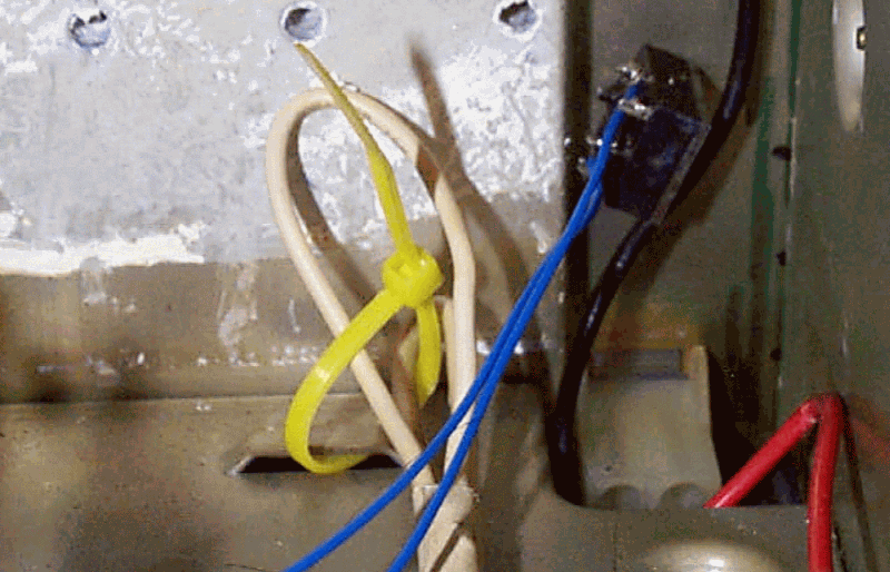
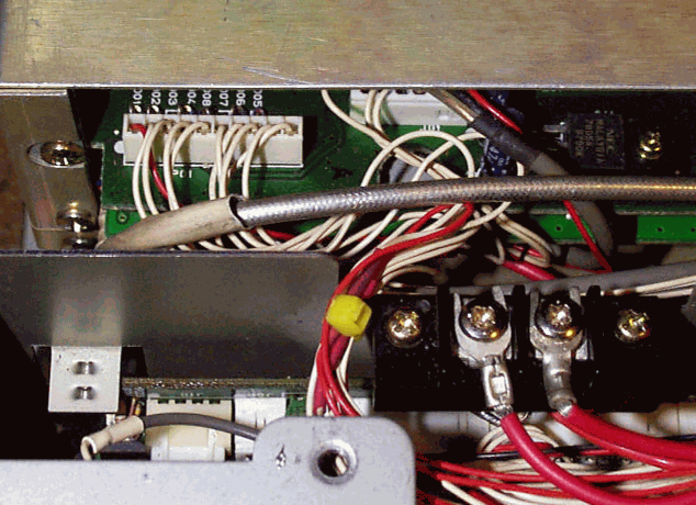
The TX wire is available without removing the band module. In fact this whole procedure can be done just by removing the bottom cover. When looking from the front to the rear of the 736 you will see a 10 position plug/jack on your left in the module. Pin 1 ( a red wire) is on the left next to the wall of the 1296 module. Count over to 6 and that is the TX line. I spliced the two ends and covered them with heat shrink tube and secured the splices with a tie wrap. The wires are routed to the new interface board.
Some additional views of the 736 and amplifier

Testing the interface
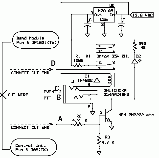
The operation is +5 from the control unit goes to A, Q1 conducts pulling B near ground, starting the sequencer. The sequencer sends a ground back to C when it gets to event 3 grounding the relay coil connrcted to C. When the contacts of K1 close, the +5 from the 78L05 is sent to the TX line going to the 1296 band module at D.
The operation is +5 from the control unit goes to A, Q1 conducts pulling B near ground, starting the sequencer. The sequencer sends a ground back to C when it gets to event 3 grounding the relay coil connrcted to C. When the contacts of K1 close, the +5 from the 78L05 is sent to the TX line going to the 1296 band module at D.
Put 12 volts to the interface board and a meter between D and ground. There should be no voltage here. The 736 control unit does not send a ground to the band module. The same is true here, we either send 5 volts or nothing. Ground C, and you should see 5 volts on the meter between D and ground.
Remove the ground on C.
Leaving 12 volts connected, make a connection between C and B. The meter should show no voltage at D. Connect +5 volts from the 78L05 to A. The meter should show 5 volts between D and ground., and when the +5 is removed from A, the meter should show nothing again. That's it !
Just keep in mind the sequencer wants to see a ground to initiate the sequence, and the sequencer sends back a ground from each event. The 736 sends a +5 to the band module on the TX line, and the band module wants to see +5 volts to transmit. The 736 doesn't want to see +12 or ground, so don't send 12 volts to the band module or ground the TX line. Either +5 or nothing. You've been warned !!!!
*NOTE Operating the 736 without the sequencer ( as original) requires a stereo jack to be installed with the tip and ring shorted to restore the TX line.
Other Methods
OH5IY
http://www.kolumbus.fi/oh5iy/HW/Yaesu.html
and lifted from AMSAT BB
I've received numerous requests for an explanation of the way that I protect
my Drake 2880 from accidental destruction while using it with my (muTek
modified) FT-736R.
What follows is from personal experience. I have been using my Drake since
late 1997 with no problems. Your mileage may vary!
There are several documented ways to inhibit transmit on a Yaesu FT-736R.
Most involve disabling drive output. (My favorite is OH5IY's TX delay mod.)
This is a global procedure. i.e. it disables _all_ band modules. While this
is fine for terrestrial work, if this is your only satellite radio, you need
the drive for your uplink so you can't globally disable it.
The key is to isolate the TX-9v line to the band you wish to disable. In this
case, 2M. For those of you with service manuals, it's easy to spot the TX-9v
line. It's clearly labeled entering the 144 MHz P.A. Unit. There is, however,
a rub! Or as a friend says, "Yaesu threw a spanner in the works". The 5 lines
that enter the 2M P.A. do so through feed thrus. If you take the top off your
radio and look at the left hand side of the rear heat sink, you'll see the 5
feed thrus for 2M. 5 on the left side are 2M and 5 on the right side are 70
cm. Now here's the rub. There is a small circuit board attached to 2 of the
feed thrus and 5 wires going to the board!! What the heck is this???
Try as I might, I couldn't locate this circuit board in the service manual. I
called Yaesu. They didn't know what I was talking about. Anyway, I finally
obtained Yeasu's docs on this "performance modification". On early 736R's
there was "heat buildup" problem in sat mode that was solved with this little
board. It's called the "TX 9v switch unit".
If you put a voltmeter on the wire that is connected to the upper right hand
corner of this little board (it's above the feed thru that is second from the
left) you'll see this line go to 9v when you transmit. This is the line to
open when you want to inhibit xmit on 2M. On my rig, this line is orange.
I did some quick and dirty tests of 2M output power with this line
enabled/disabled.
First, with everything enabled:
Drive control at max = 27 watts
Drive control at min = 2.7 milliwatts
Disabled TX 9v line:
Drive control at max = 27 microwatts
Drive control at min = .0027 microwatts (I don't really trust my test gear
this low :-} )
On my system, I use a 20 dB pad in between the Drake and rig to get the S
meter near S0. Also, I run 75 feet of RG-58 down the tower. So in addition to
the numbers above, subtract 24 dB. Worst case scenario for me is that I
transmit full drive with inhibit on and the signal will be -84 dB down from
27 watts or ~ .1 microwatt.
Similar procedures work for the FT-290R MKII. Hope this helps.
73,
Mike, N1JEZ
AMSAT #29649
Local Area Coordinator
"A closed mouth gathers no feet."
----
Via the amsat-bb mailing list at AMSAT.ORG courtesy of AMSAT-NA.
Thanks to Richard, K4RTS for this one......
1. Remove the top cover from the 736.
2. Locate the Transmit Unit board - it will be the be one of three
horizontal circuit boards on top. . . the Transmit Unit is the one on the
far left hand side.
3. Locate jack J10 (has 6 leads on it) which is in the back right hand
corner of the board. Pin 3 of J10 has an orange lead attached.
4. Grounding this lead will inhibit the unit from transmitting any RF.
5. Nick the insulation of the orange lead and solder on a small wire.
6. Carefully remove the Receive Unit located on the far left hand side of
the radio. This board mounts vertically (stands on it's side).
7. Solder the other end of the lead the goes to the orange wire on the
Transmit Unit (from step 5) to the unused pin 5 of the CAT DIN plug.
I then tie pin 5 of the CAT DIN plug to one of the relay contacts in my DEM
sequencer. I tie the 736 PTT in/out to the PTT input on the DEM sequencer.
I also use pin 6 of the CAT DIN jack to provide 13.8 vdc supply voltage to
the sequencer.
Remember, a ground on CAT DIN pin 5 (once the 736 is modified) inhibits the
736 from transmitting RF. I have the DEM sequencer set up so that it keeps
a ground on this lead at all times until I begin the transmission sequence.
The relay in the sequencer pulls up about 500 ms after I initiate PTT (and
releasing the ground), thus allowing the 736 to transmit after everything
else has had a chance to switch. 500 ms is more delay than I really need,
but it doesn't hurt anything.
- --------------------------------
73,
Mike, N1JEZ
AMSAT #29649
AMSAT Local Area Coordinator
"A closed mouth gathers no feet."
----
Via the amsat-bb mailing list at AMSAT.ORG courtesy of AMSAT-NA.
back